1.Introduction
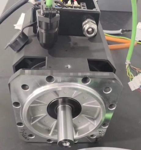
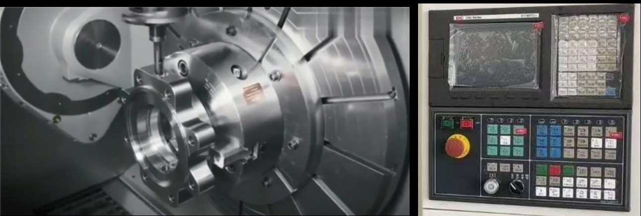
Synchronous electric spindles are characterized by low rotational inertia, high dynamic response, compact size, and high power density. Electric spindles integrate the machine tool spindle and the spindle motor, overcoming the drawbacks of traditional mechanical spindles such as slipping, vibration, high noise, and large inertia at high speeds. They effectively improve the overall performance of spindles in high-speed conditions and are widely used in the field of CNC machine tools.
2.Technical Requirements and Classification of High-Speed Electric Spindls
High-speed electric spindle technical requirements:
-Maximum operating frequency of 4000Hz
-Open-loop/closed-loop operation
-Smooth start/stop without jitter, short acceleration and deceleration time
-Weak magnetic zone control of permanent magnet synchronous high-speed spindle to avoid driver faults
-Minimal speed fluctuation during high-speed operation
-Low motor vibration speed during operation
-High reliability, suitable for harsh operating environments
The spindle is classified according to the purpose:
| Application | Usage | Characteristics |
Engraving and milling | CNC milling machine,Machining center | Possesses high-speed, high precision, and low-speed high torque characteristics; Equipped with accurate speed control, precise stopping, and zero-speed locking functions. |
Grinding | Grinding machine | Mainly adopting constant torque electric spindle; Possessing high speed and high precision characteristics. |
Drilling | Drilling machine | High axial rigidity; Possessing high speed and high precision characteristics. |
3.Debugging
(1)Drive selection description
Spindle end: Motor type, nominal frequency, speed, current value
Encoder end: Differential, push-pull, rotary variable, UVW encoder PG card, ECN1313, sine-cosine encoder PG card
Host computer end: Analog input, pulse input, communication

Equipment model
(Motor model provided by the manufacturer)
FRECON inverters | ||||
Name | Voltage Level | Model | Current | Quantity |
Inverters | 380V | FR510S-4T-011G/015PB | 25A | 1PCS |
PGcard | - | EXC-PG06 (sine-cosine encoder PG card) | - | 1PCS |
Resistance | - | 1.1KW 50Ω | - | 1PCS |
(2)Inverter wiring diagram

The wiring diagram for high-speed electric spindle frequency converter control
(3)Commissioning Instructions
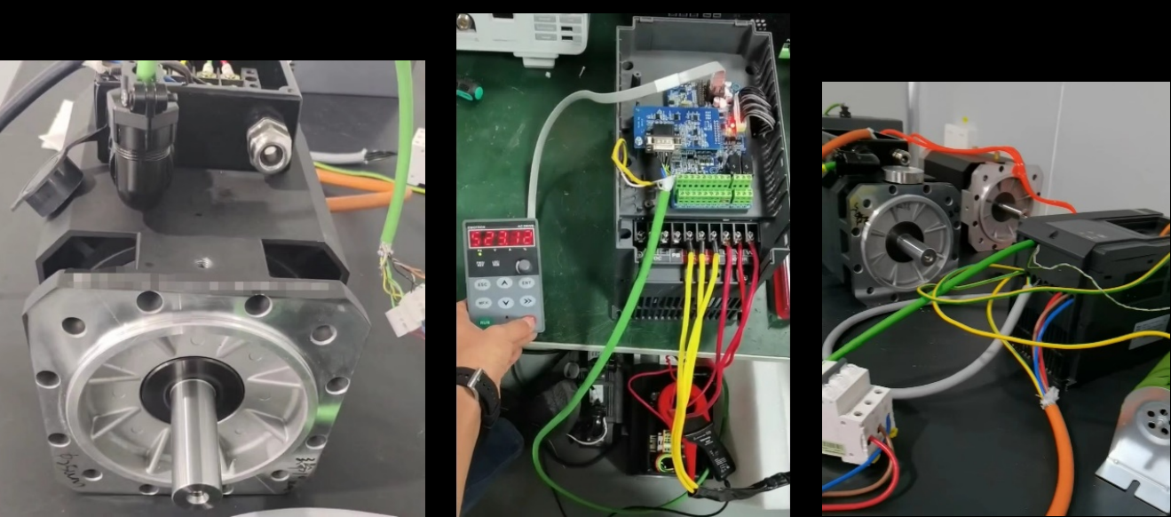
1) Verify the wiring according to the electrical schematic diagram.
2) Perform self-learning with input motor parameters.
3) Conduct initial testing under no-load conditions to assess speed response, and adjust speed and position loop gains as necessary.
4) Once the no-load testing is satisfactory, proceed to load testing and fine-tune the parameters based on actual performance.
(4)Main parameter settings for the inverter
Function Code | Name | Parameter Value | Explanation |
F00.08 | Motor control mode | 13 | PG Vector Control |
F00.13 | Carrier frequency | 0.7~16KHz | Adjust according to the situation |
F01.08 | Maximum frequency | 20~4000Hz | Adjust according to the maximum frequency of the motor |
F01.09 | Maximum frequency | Maximum frequency value | Adjust according to the maximum frequency of the motor |
F03.00 | Accel time | 1S | Adjustable from 0.8 seconds to 6000 seconds as required |
F03.01 | Decel time | 1S | Adjustable from 0.8 seconds to 6000 seconds as required |
F08.00 | Motor type selection | 1 | Synchronous motor |
F08.01 | Power rating of motor | 0.1-1000KW | Adjust according to the rated power of the motor |
F08.03 | Rated current of motor | 0.1~1500A | Adjust according to the rated power of the motor |
F08.04 | Rated frequency of motor | 20~Fmax | Adjust according to the rated frequency of the motor |
F08.05 | Rated speed of motor | 1-30000 | Adjust according to the rated speed of the motor |
F08.23 | Encoder line number | 0·65535 | Adjust according to the number of encoder lines |
F08.24 | Encoder type | 0~4 | Select the encoder type |
F08.30 | Autotuning of motor | 2 | Rotary autotuning of motor |
(5)Comparison of Electric Spindle Vibration
Speed rpm | FRECON driver | Leading brands | ||
Front bearing vibration mm/s | Rear bearing vibration mm/s | Front bearing vibration mm/s | Rear bearing vibration mm/s | |
2000 | 0.18 | 0.12 | 0.03 | 0.04 |
4000 | 0.14 | 0.15 | 0.14 | 0.05 |
6000 | 0.13 | 0.17 | 0.14 | 0.05 |
8000 | 0.15 | 0.18 | 0.22-0.24 | 0.12-0.14 |
10000 | 0.14 | 0.19 | 0.18 | 0.08-0.09 |
12000 | 0.15 | 0.15 | 0.19 | 0.11-0.13 |
14000 | 0.2 | 0.13 | 0.24 | 0.11 |
16000 | 0.18 | 0.15 | 0.27 | 0.09-0.1 |
18000 | 0.15 | 0.13 | 0.28 | 0.12-0.14 |
20000 | 0.13 | 0.17 | 0.32-0.33 | 0.13-0.15 |
22000 | 0.14 | 0.12 | 0.34-0.35 | 0.13-0.16 |
24000 | 0.15 | 0.15 | 0.35-0.37 | 0.15-0.16 |
26000 | 0.18 | 0.15 | 0.35-0.37 | 0.14-0.17 |
28000 | 0.2 | 0.15 | 0.35-0.37 | 0.15-0.18 |
Frecon frequency converter has low vibration in high frequency operation, reaching the industry-leading level.
4.the application advantages of FR510S inverter
The FR510S inverter is an special drive designed for high-speed spindles. It features a wide speed range, fast response speed, and high control accuracy. In particular, it has the advantages of fast response speed (only 0.8s for acceleration and deceleration to 25,000 rpm) and high control accuracy (error under closed-loop vector control is as low as 0.025%, and motor vibration speed is below 0.2mm/s), ensuring smooth operation of high-speed electric spindles.
5.Summary
The application of FR510S in high-speed electric spindles successful has provided a domestic solution for the synchronous electric spindle industry. The FR510S inverter from FRECON has demonstrated high control accuracy, easy operation, convenient maintenance, and low failure rates, indicating that it can be applied in similar high-frequency industries.
6.FR510S series picture appreciation


