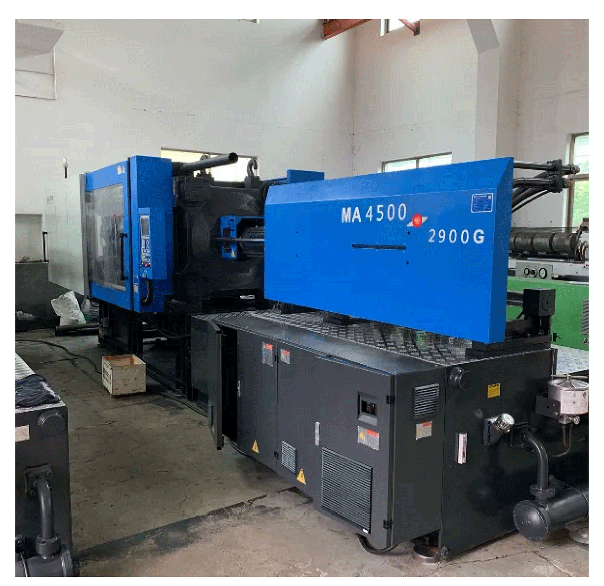
The plastic industry is developing rapidly, and the injection molding industry is also embracing a tremendous growth opportunity. Among the various plastic processing methods, injection molding machines are the most widely used. However, they consume a large amount of energy, and the competition within the industry is becoming increasingly fierce. In addition to focusing on product quality and brand, manufacturers are paying more attention to controlling production costs. With the promotion of variable frequency technology, variable frequency speed regulation has become widely applied in transmission control and energy saving. The introduction of inverters into injection molding machines can reduce energy consumption, improve work efficiency, and achieve energy savings (approximately 30% to 50%, depending on the product processing conditions). The inclusion of inverters plays a significant role in improving product quality, reducing noise pollution, enhancing reliability, and extending the service life of motors.

The injection molding machine is primarily used for producing plastic parts. Conventional injection molding machines typically use hydraulic transmission and are widely applied in fields such as defense, electricity, electronics, electrical appliances, and daily necessities. Its structure is shown in the figure below and mainly consists of four parts: the injection unit, the clamping unit, the hydraulic transmission unit, and the electrical control system.
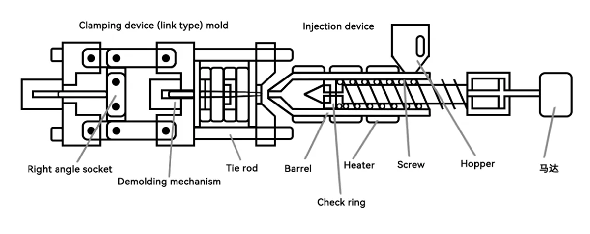
Injection Unit: The injection system includes the hopper, barrel, heater, metering device, and screw (in plunger-type injection molding machines, it consists of the plunger and diverter shuttle). The injection system is responsible for heating and melting the plastic, bringing it to a viscous flow state, and applying high pressure to inject it into the mold cavity.
Clamping Unit: This unit mainly consists of the front and rear fixed platen, moving platen, tie bars, clamping cylinder, linkage mechanism, mold adjusting mechanism, and product ejection mechanism. The clamping system is responsible for closing, locking, opening the mold, and ejecting the molded product.
Hydraulic Transmission Unit and Electrical Control System: These systems ensure that the injection molding process operates accurately according to the specified process parameters (such as pressure, speed, time, temperature) and program requirements.

The injection molding process is a cycle-based operation, which includes the following steps: 【clamping - mold locking - nozzle advancement - injection - holding pressure - cooling - pre-plastification - injection unit retreat - mold opening - product removal, etc.】 to achieve the molding of a product.
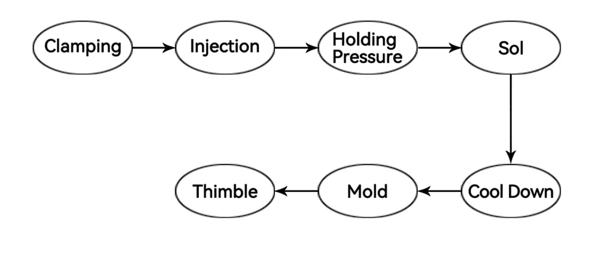
Mold Locking: The mold platens quickly approach the fixed platen (including slow-fast-slow movements), and once it is confirmed that there are no foreign objects present, the system switches to high pressure to lock the mold platens together (maintaining pressure in the clamping cylinder).
Injection Unit Forward: The injection unit moves forward to the designated position (with the nozzle in close contact with the mold).
Injection: The screw can be set to multi-stage speed, pressure, and stroke to inject the molten material into the mold cavity at the front end of the barrel.
Cooling and Holding Pressure: Maintain the pressure in the barrel according to multiple preset pressure levels and time segments, while the mold cavity cools and solidifies the molded part.
Cooling and Preplastication: The product inside the mold cavity continues to cool, while the hydraulic motor drives the screw to rotate, pushing the plastic pellets forward. The screw retracts under the preset backpressure control. When the screw retreats to the predetermined position, the screw stops rotating, and the injection cylinder is released according to the preset settings, completing the pre-plastication.
Injection Unit Retreat: After pre-plastication is complete, the injection unit retreats to the designated position.
Mold Opening: The mold plate retracts to its original position (including slow-fast-slow movements).
Ejector Pins: The ejector pins push out the molded product.

Overflow Loss: Depending on the product and processing procedures, different steps require varying amounts of hydraulic pressure, flow, and pressure. Therefore, the load on the oil pump motor during the injection molding process is in a state of constant change. The pump's flow rate is designed based on the required maximum flow. The oil pump provides a constant hydraulic flow at a fixed speed. When the required flow is less than the maximum flow, the excess hydraulic pressure is returned through the overflow valve, resulting in energy loss.
Throttle Loss: When hydraulic oil flows through the throttle port of a valve, there is a certain pressure drop, which is known as throttle loss. Since the throttle area of directional valves is relatively large, most of the throttle loss occurs in the proportional valve. Additionally, due to the long-term full-speed circulation of the hydraulic fluid and the intense mechanical friction in hydraulic components, issues such as excessive oil temperature, high noise, and shortened mechanical lifespan can occur.
Design Margin Loss: In typical designs, versatility is often considered, and the design is based on the maximum capacity. As a result, the capacity of the user's pump motor is usually much higher than what is actually required, leading to the "oversized motor for a small load" phenomenon. This causes significant waste of electrical energy.

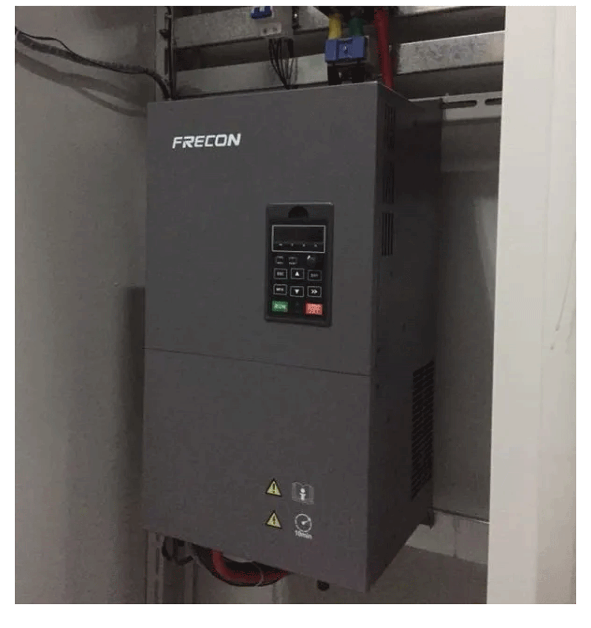
For the injection molding process and its technical characteristics, FRECON designed the FR500A series inverter with a dedicated expansion card to control the oil pump motor. This solution not only enhances the reliability and service life of the equipment but also saves significant energy consumption, greatly improving the company's economic efficiency and market competitiveness.

1. It features a dedicated operating frequency channel for injection molding machines, with a control accuracy of ±0.2% and 0.5Hz. It provides 180% starting torque, short acceleration and deceleration times, and a fast system response.
2. It supports closed-loop control of the oil pump speed and start/stop operations, enabling soft start of the motor to reduce impact and vibration on the equipment.
3. The temperature rise of the injection molding machine hydraulic oil is significantly reduced, which greatly extends the equipment's service life. Additionally, excess energy consumption during no-load and low-pressure oil pump conditions is saved.
4.The system has strong current suppression capabilities, effectively preventing faults such as overcurrent, ensuring stable system operation.
5.The system demonstrates significant energy-saving effects, typically achieving energy savings of 30% to 50%
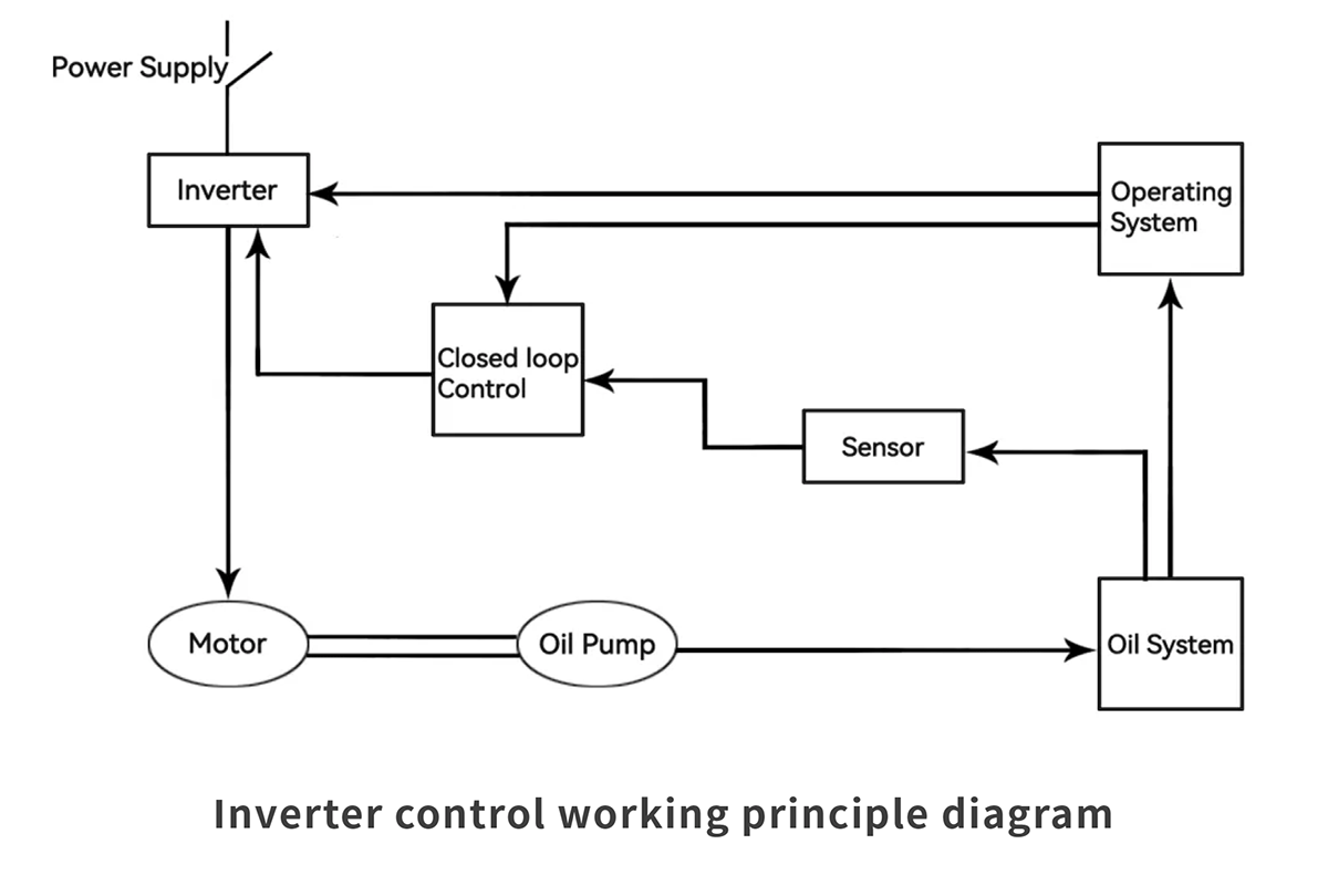
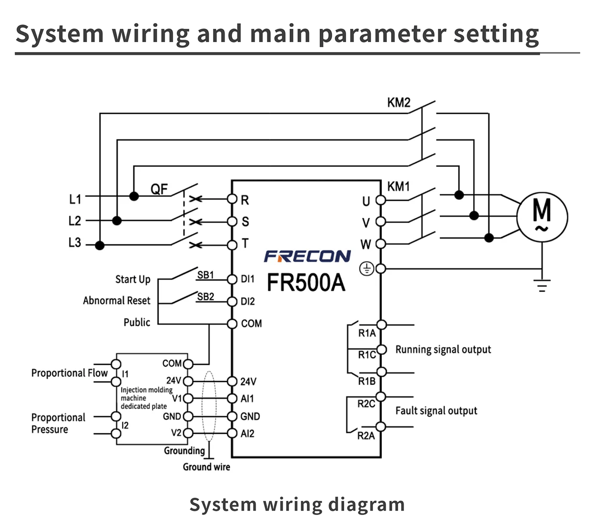
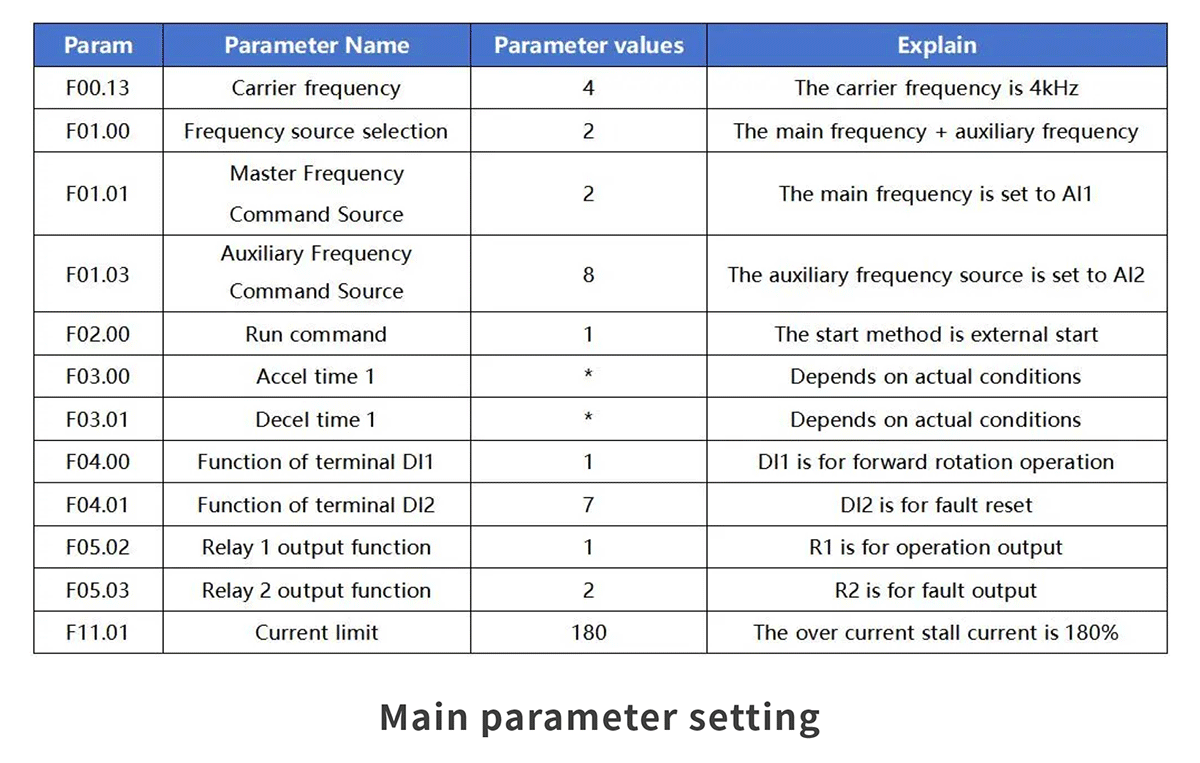

This article introduces the injection molding machine drive solution based on the FRECON FR500A series inverter. The solution features advantages such as short acceleration and deceleration times, fast system response, and stable system operation. It also demonstrates significant energy-saving effects, with a noticeable reduction in the hydraulic oil temperature rise, effectively extending the service life of the hydraulic oil. This solution has already been successfully applied in multiple injection molding machine energy-saving retrofit projects.
