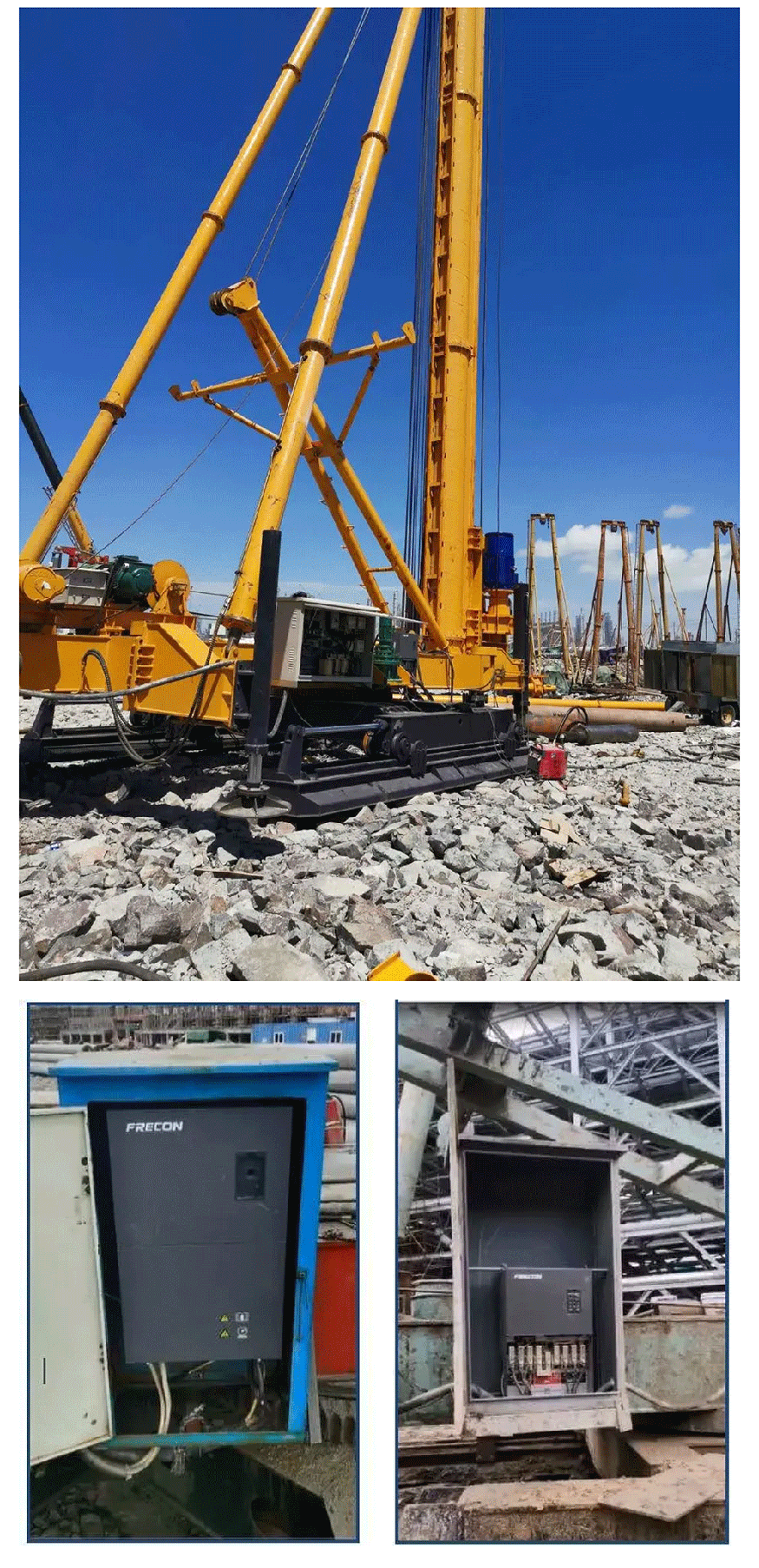
In recent years, our country has made substantial investments in infrastructure, particularly in the construction
industry. Among these, pile drivers play an indispensable role; whether it’s for overpasses, interchanges, or
cross-river bridges, they are everywhere.

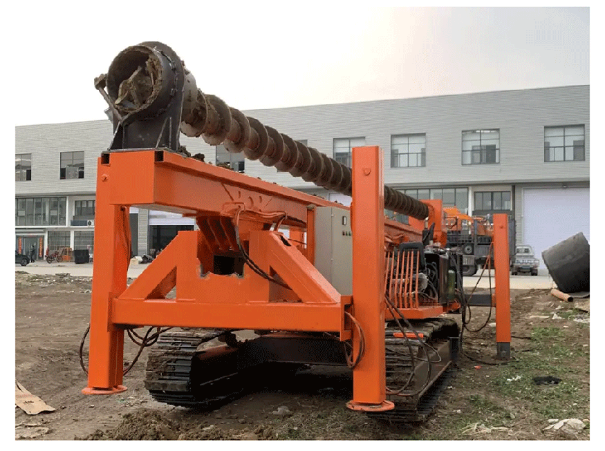
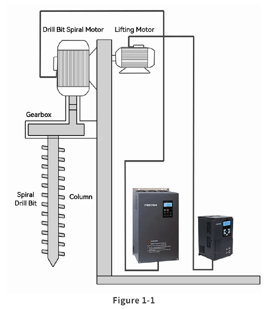
A spiral pile driver (as shown in Figure 1-1) is a construction piling device that drills holes into the ground through
the rotation of a drill rod driven by a power head. Traditional pile drivers use diesel hammering (also known as diesel
hammers), which consists of a cylinder and a plunger. This method uses the powerful pressure generated by the
explosion of atomized diesel injected into the cylinder’s combustion chamber under high pressure and temperature
to drive the hammer head. This method is noisy, causing disturbances to residents, and the exhaust gases and oil leaks
from diesel combustion can lead to environmental pollution. Newer pile drivers use inverters to drive the motor,
eliminating noise, improving workers' comfort, and reducing environmental pollution, which greatly enhances production efficiency.

(1) Inverter requirements
Strong overload capability
Smooth torque output
High vibration resistance and environmental adaptability
(2) Components
Pile Frame Section
Drilling Section
Control and Operation Section
(3) Piling technology
The piling process is as follows: position the spiral pile driver, install the casing, start drilling once the drill bit lightly
touches the ground by rotating it, lower the drill bit, complete the hole, clean it and measure the depth, insert the
rebar cage and conduit, pour the concrete, remove the casing, clean the pile head, backfill, and complete the pile.
Note: In some cases, the drill bit rotation is driven by two motors. In such cases, it is recommended to use two
inverters to drive the motors separately. The inverters should communicate via RS485 to achieve synchronized
control of output frequency, current, and speed.

Composed of the power supply box, control box, and operation panel.
The system uses two FRECON inverters to control the equipment: one for driving the drill bit lifting mechanism and the other
for driving the drill bit rotation mechanism. The drill bit lifting mechanism is driven by a FR500A-4T-045G/055PB inverter, which
should provide forward and reverse control as well as smooth switching between high, medium, and low speeds.
It also needs to be equipped with an energy-saving braking unit and a braking resistor to eliminate the reverse energy generated
by the motor during the drill bit's descent. The drill bit rotation mechanism is driven by a FR500A-4T-132G/160P inverter that controls
a 110 kW motor.

Includes overload, rope break, short circuit, and overspeed safety switches in the circuitry. Each door on the hoist cage is equipped
with limit switches, and a cone-type speed limiter is installed as a fall protection device.
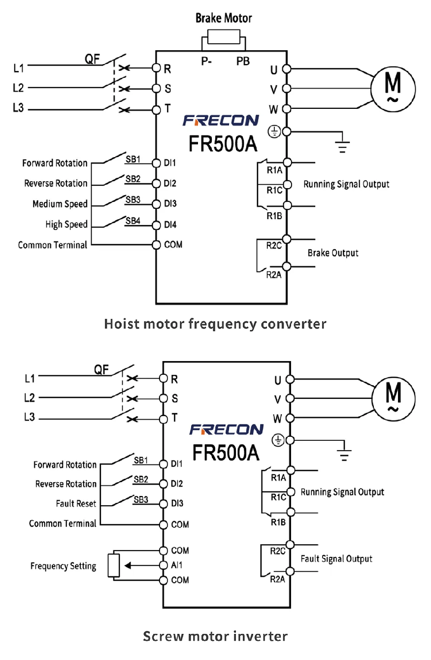

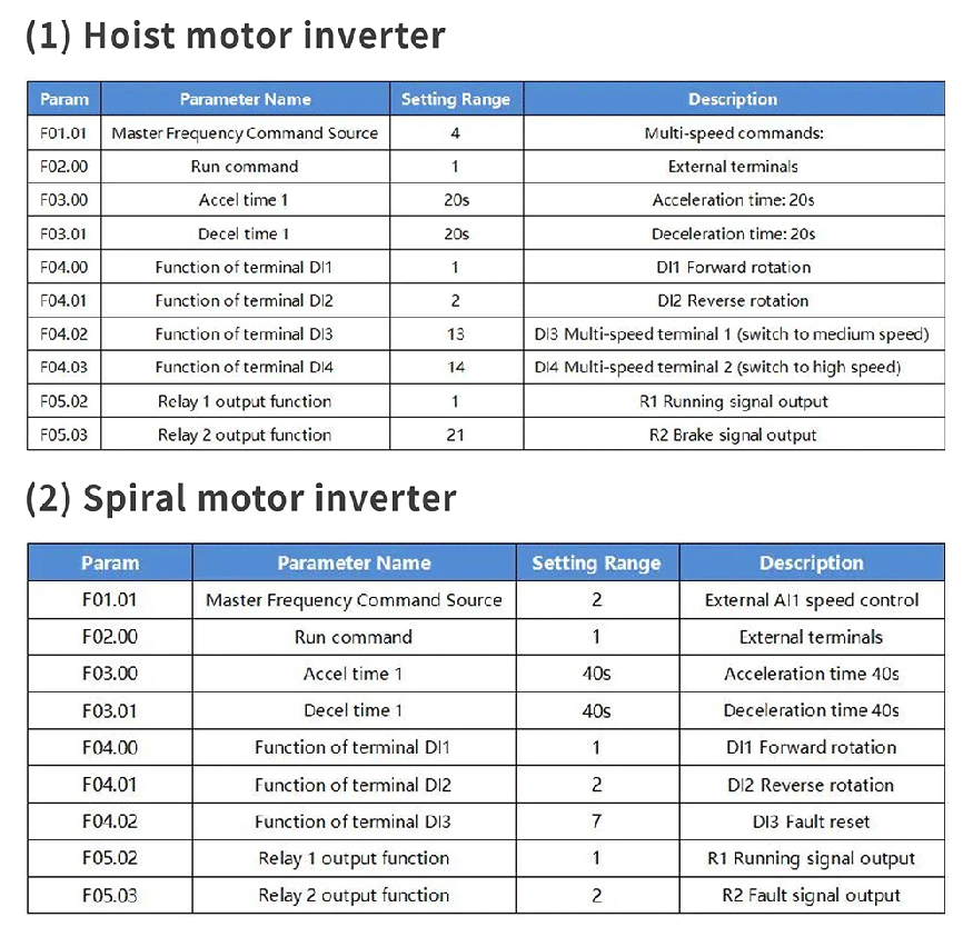
Note: If the inverter and motor power are inconsistent (or if the motor is not a four-pole motor), it is
recommended to enter the motor parameters into the inverter parameter group F08.01-F08.05.

(1) Achieves smooth and stepless acceleration and deceleration, improving system safety.
(2) Variable frequency speed control technology greatly enhances system efficiency, reduces production costs, minimizes noise
pollution, and achieves zero emissions.
(3) Excellent open-loop vector control algorithm ensures smooth low-frequency heavy-load startup, stable output current and torque,
and enables extraction of the drill rod after stopping under abnormal conditions.

