Elevator performance depends on more than motor speed or travel time; the quality of the electrical power supplied to the drive also matters. Current ripple can increase electrical stress, contribute to electromagnetic interference, and affect system efficiency if it is not managed appropriately.
Engineers evaluating an elevator VFD should consider the entire power path, from the incoming supply and DC bus to the motor and its control strategy. At FRECON, we recognize that dependable drive applications require attention to both electrical behavior and the demands of the installation.
Understanding Where Current Ripple Comes From
Current ripple refers to the periodic variation superimposed on an electrical current. In variable-frequency drive systems, switching devices rapidly turn on and off to regulate power, creating high-frequency current components. The magnitude and frequency of these components depend on the converter topology, switching strategy, inductance, load, and electrical impedance.
The DC-link circuit plays an important role. Capacitors help smooth voltage variations, while inductors can limit changes in current. If the DC bus has insufficient filtering or the supply contains significant distortion, ripple may increase. Component aging, loose connections, and unsuitable system design can also affect electrical stability, making measurement and inspection important during troubleshooting.
Elevator duty cycles create additional considerations. Frequent starts, stops, acceleration, deceleration, and changing passenger loads produce varying power demands. Regenerative systems may return energy to the DC bus during braking, while non-regenerative configurations manage that energy differently. Engineers working with elevator inverter systems should distinguish normal switching-related ripple from abnormal fluctuations caused by supply issues, component faults, or control instability.
Selecting Filtering and Power-Stage Solutions
Filtering components must be selected according to the electrical design rather than added indiscriminately. DC-link capacitors can reduce bus-voltage fluctuations, while AC line reactors may help limit input-current distortion and reduce the effects of supply transients. Output reactors and suitable filters address different issues on the motor side, so their placement and purpose should be clearly defined.
Switching frequency also influences ripple. Higher switching frequencies can reduce certain current harmonics, but they may increase switching losses and heat generation. Lower frequencies can improve some aspects of thermal performance while producing different acoustic or electrical effects. The appropriate setting depends on the drive design, motor characteristics, installation conditions, and the manufacturer’s permitted operating range.
Component sizing requires attention to more than nominal current. Engineers should consider transient loads, harmonic content, temperature rise, voltage ratings, and expected service conditions. Experienced VFD manufacturers typically provide installation instructions and electrical specifications that help system designers determine whether additional filtering is needed. Changes should be validated against the drive’s documentation because an unsuitable component arrangement can introduce resonance or interfere with normal operation.
Coordinating Motor Control With Elevator Duty
Smooth elevator movement depends on coordinated control of torque, speed, and braking. During acceleration, the drive must provide sufficient torque to move the car and counterweight while keeping the ride comfortable. During deceleration, it must manage the changing energy flow without causing excessive DC-bus voltage or unstable motor behavior.
Control tuning can influence current fluctuations. Acceleration ramps, torque limits, speed-loop settings, and current-control parameters should reflect the elevator’s mechanical characteristics and rated load. Poorly tuned loops may create oscillation or abrupt torque changes, whereas excessively conservative settings can lengthen travel times or reduce responsiveness. Adjustments should be performed methodically by qualified personnel.
Electrical compatibility is equally important. Motor ratings, cable length, grounding, shielding, and the quality of incoming power all affect system behavior. A properly configured elevator VFD must operate within its electrical and thermal limits while meeting the elevator’s performance requirements. Commissioning should therefore include checks under representative load conditions rather than relying exclusively on unloaded testing.
Measuring Ripple and Verifying Performance
Reliable diagnosis begins with suitable instruments and a defined measurement method. Power-quality analyzers, oscilloscopes, and appropriate current probes can reveal different aspects of electrical behavior. The selected equipment must have sufficient bandwidth and ratings for the circuit being examined, and measurements around energized drive systems should be performed only by trained professionals following relevant safety procedures.
Comparisons are meaningful only when test conditions are consistent. Record supply voltage, operating frequency, motor load, switching settings, and the point at which measurements are taken. Input-side current distortion, DC-link ripple, and motor-side current variation are different quantities; treating them as interchangeable can lead to incorrect conclusions about system performance.
Applying Design Principles to Real Equipment
System-level testing helps confirm whether a ripple-reduction measure actually improves operation. An adjustment that lowers one measured harmonic may increase losses elsewhere, so engineers should review current quality, thermal behavior, electromagnetic compatibility, and ride performance together. The final configuration should reflect the priorities of the specific elevator rather than a single isolated metric.
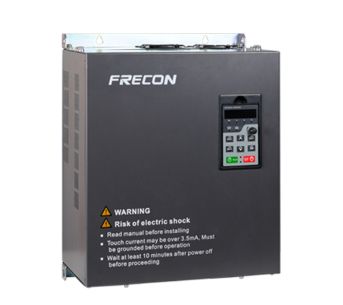
Product specifications also establish the limits of a design. FRECON’s SY380 series voltage boost inverter is specified for single-phase 220 V input applications in the 4.0 kW to 22 kW range. This information can help determine whether the product’s stated electrical class is relevant to a proposed application, but the available specifications alone do not establish elevator suitability or a particular ripple level. Detailed compatibility, control functions, and applicable certifications must be confirmed before selection.
Conclusion
Current ripple management calls for a balanced approach that combines circuit design, filtering, control tuning, and measured verification. No single component or parameter can address every source of electrical variation, especially in elevator systems with frequent changes in load and operating state.
At FRECON, we believe that application-specific evaluation and careful commissioning provide a sound basis for dependable motor-control performance. Selecting an elevator inverter or an elevator VFD should involve verified electrical compatibility, clear technical data, and a test plan that reflects real operating conditions.