Fast-changing loads expose the real capabilities of industrial drive systems. Speed commands, torque demands, and operating conditions can shift within seconds, leaving little room for unstable responses or excessive recovery time. For engineers evaluating a variable frequency drive manufacturer, dynamic response verification offers a practical way to assess whether control performance remains consistent across different operating scenarios.
At FRECON, we approach drive development with attention to measurable performance, application requirements, and dependable operation, recognizing that scaling inverter technology requires more than increasing power capacity.
Defining Dynamic Response Under Real Operating Conditions
Dynamic response describes how quickly and accurately a drive reacts when its operating target changes. Typical disturbances include sudden load increases, abrupt speed references, supply-voltage fluctuations, and transitions between operating modes. Each condition reveals different aspects of the control system, so one successful test cannot represent every application.
Response time is only one part of the assessment. Engineers also examine overshoot, settling time, steady-state deviation, and oscillation after a command changes. A drive that reaches its target quickly but produces excessive speed fluctuation may perform worse in a precision process than one with a slightly slower yet more stable response. Test criteria should reflect the consequences of these behaviors in the intended machinery.
Consistent evaluation also requires repeatable starting conditions. Motor parameters, load inertia, acceleration settings, control-loop gains, and measurement methods can all affect the results. A general-purpose inverter may serve pumps, conveyors, fans, and other equipment with very different response demands; standardized procedures help distinguish genuine control improvements from differences in test setup.
Establishing Repeatable Verification Procedures
Reliable testing begins with a defined baseline. Engineers should record motor ratings, drive settings, firmware versions, supply conditions, load characteristics, and ambient temperature before comparing results. Without this information, two measurements that appear comparable may reflect different operating conditions rather than actual changes in performance.
Step-response testing provides one useful method. The speed reference is changed by a specified amount, and the resulting motor behavior is recorded over time. From the response curve, evaluators can calculate rise time, peak overshoot, and settling time. Load-step testing adds another dimension by changing the mechanical demand while holding the speed command constant, revealing how effectively the drive compensates for disturbance.
Repeatability matters as much as the initial result. Tests should be conducted several times under equivalent conditions, with deviations recorded rather than concealed by averaging. A vector control inverter can be assessed through speed tracking, torque response, and low-speed stability, provided that the test plan accounts for motor characteristics and the feedback configuration used. Acceptance limits should come from application requirements or an applicable technical specification, not from arbitrary universal thresholds.
Assessing Control Accuracy During Rapid Transitions
Dynamic performance depends on how the controller responds to the difference between the commanded state and the measured or estimated motor state. In vector control, the system separates motor-current components associated with magnetic flux and torque, enabling more independent regulation than basic scalar control. The quality of parameter identification and current regulation strongly influences the resulting response.
Measurement equipment must capture the behavior being investigated. Sampling rates that are too low can miss short-lived peaks, while poorly synchronized signals may distort the apparent relationship between a command and the motor response. Speed, current, torque where measurable, and DC-bus voltage can provide complementary evidence. Engineers should also document sensor accuracy, signal filtering, and any delay introduced by the measurement chain.
Different applications call for different priorities. A conveyor may need to recover smoothly from a sudden load change, while a winding machine may be particularly sensitive to speed deviation and tension variation. During performance reviews, a variable frequency drive manufacturer should evaluate these operating needs against measurable test results instead of relying on a single headline response figure. Clear test records make it easier for engineering teams to judge whether a drive is suitable for a specific duty cycle.
Scaling Verification Across Power Ratings and Applications
Increasing drive capacity can change the electrical and mechanical conditions under which the control system operates. Larger motors may have different inertia, current requirements, and parameter sensitivities, so performance demonstrated on one rating should not automatically be assumed for every model in a series. Verification plans need to cover representative configurations and identify the limits of any conclusions drawn from those tests.
A practical scaling strategy combines type testing with targeted validation. Type tests examine representative hardware and control functions in depth; subsequent checks confirm that related models retain the required behavior. Testing should also consider operating boundaries, including low-frequency operation, rapid acceleration, regenerative events where supported, and transitions between control modes. Results should be traceable to the exact hardware and software configuration tested.
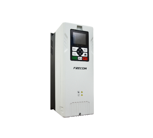
Our FR30 Series High Performance Inverter is designed for applications requiring accurate speed regulation, responsive torque control, and strong low-frequency output characteristics. Its built-in VC, SVC, and VF control options support different control approaches within a flexible industrial drive platform.
For engineering teams, the relevant verification task is to match the selected mode to the motor and load, then validate performance using documented operating conditions rather than assuming identical behavior across every application.
Conclusion
Dynamic response verification turns broad performance claims into evidence that engineers can compare and reproduce. Well-defined test conditions, suitable measurement equipment, repeated trials, and application-specific acceptance limits help expose weaknesses that routine operation may not reveal. Scaling control technology successfully also requires careful validation across power ratings, motor combinations, and operating modes.
At FRECON, we view this evidence-based process as an important part of developing dependable drive solutions. A general-purpose inverter should be evaluated against its intended duty, while a vector control inverter requires particular attention to torque behavior, speed stability, and control configuration. Applying these principles gives engineering teams a clearer basis for selecting and validating industrial drives.